circuit diagram of rfid based toll collection system As an educational project, we are going to make a basic system where each vehicle will have a preregistered unique ID (using an RFID card). When the driver arrives at the toll plaza, the driver punches the ID to a specific .
NFC/RF reader and writer app very easy to use.Just hold the NFC/RF card .
0 · rfid toll gate
1 · rfid toll collection system
2 · automatic toll gate system
3 · arduino toll gate
At 13.56 MHz, Cant value gets in the range of some pF and LA > Lant. The antenna .
Automated toll collection system using RFID introduces the Automatic Smart Toll Tax Collection System, employing an RFID Module and Arduino. With the increasing congestion at toll .In this paper, we present the design and implementation of an RFID-based toll collection system using Arduino microcontroller boards. The proposed system leverages Radio-Frequency . Circuit Diagram for Toll collection system using RFID. Here is the circuit diagram which makes this project. I have given a step-by-step explanation of how to make connections .

Hey Friends In This Video I Will Show You How To Make RFID Based Automated Toll Collection System Using ArduinoCode And Circuit Diagram:- https://github.com/.
Design and implement an Arduino based Toll tax collection system utilizing RFID technology for payment and Infrared Sensor for vehicle detection. As an educational project, we are going to make a basic system where each vehicle will have a preregistered unique ID (using an RFID card). When the driver arrives at the toll plaza, the driver punches the ID to a specific .
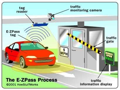
The document discusses an electronic toll collection system that uses radio frequency identification (RFID) technology. It describes the key components of RFID tags and readers that allow the system to automatically .
Here is the Rfid based arduino toll system diagram to make the circuit. The circuit is easy to make and there is no need of any breadboard here. Further to make it easier I will . Circuit diagram for Arduino RFID Barrier System With OLED Display. This is the circuit that we will use in this project, below I will explain the connections components wise. Circuit to connect Arduino uno and RFID . The circuit for RFID Based Toll Tax Collection System is given below. The circuit is based on the above flowchart with the use of necessary electronic components. The RFID .
Automated toll collection system using RFID introduces the Automatic Smart Toll Tax Collection System, employing an RFID Module and Arduino. With the increasing congestion at toll .In this paper, we present the design and implementation of an RFID-based toll collection system using Arduino microcontroller boards. The proposed system leverages Radio-Frequency . Circuit Diagram for Toll collection system using RFID. Here is the circuit diagram which makes this project. I have given a step-by-step explanation of how to make connections .
Hey Friends In This Video I Will Show You How To Make RFID Based Automated Toll Collection System Using ArduinoCode And Circuit Diagram:- https://github.com/.Design and implement an Arduino based Toll tax collection system utilizing RFID technology for payment and Infrared Sensor for vehicle detection. As an educational project, we are going to make a basic system where each vehicle will have a preregistered unique ID (using an RFID card). When the driver arrives at .
The document discusses an electronic toll collection system that uses radio frequency identification (RFID) technology. It describes the key components of RFID tags and . Here is the Rfid based arduino toll system diagram to make the circuit. The circuit is easy to make and there is no need of any breadboard here. Further to make it easier I will .
Circuit diagram for Arduino RFID Barrier System With OLED Display. This is the circuit that we will use in this project, below I will explain the connections components wise. . The circuit for RFID Based Toll Tax Collection System is given below. The circuit is based on the above flowchart with the use of necessary electronic components. The RFID .Automated toll collection system using RFID introduces the Automatic Smart Toll Tax Collection System, employing an RFID Module and Arduino. With the increasing congestion at toll .In this paper, we present the design and implementation of an RFID-based toll collection system using Arduino microcontroller boards. The proposed system leverages Radio-Frequency .
Circuit Diagram for Toll collection system using RFID. Here is the circuit diagram which makes this project. I have given a step-by-step explanation of how to make connections . Hey Friends In This Video I Will Show You How To Make RFID Based Automated Toll Collection System Using ArduinoCode And Circuit Diagram:- https://github.com/.Design and implement an Arduino based Toll tax collection system utilizing RFID technology for payment and Infrared Sensor for vehicle detection.
As an educational project, we are going to make a basic system where each vehicle will have a preregistered unique ID (using an RFID card). When the driver arrives at . The document discusses an electronic toll collection system that uses radio frequency identification (RFID) technology. It describes the key components of RFID tags and . Here is the Rfid based arduino toll system diagram to make the circuit. The circuit is easy to make and there is no need of any breadboard here. Further to make it easier I will .
rfid toll gate
rfid toll collection system
automatic toll gate system
The PN7642 is ideally suited for use with the NXP NTAG 5, an ISO/IEC 15693-based, NFC .
circuit diagram of rfid based toll collection system|automatic toll gate system