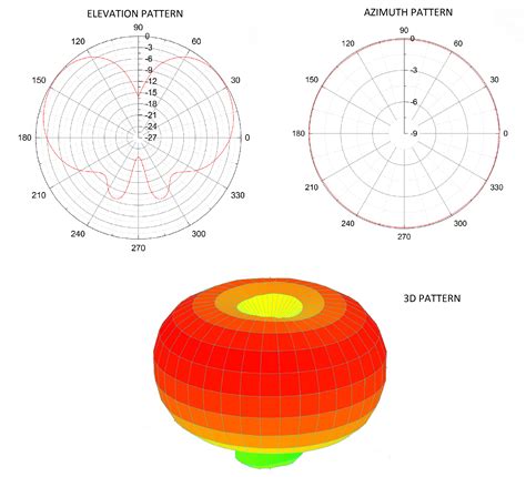
how to read rf antenna patterns RF antenna radiation patterns can be presented in several ways; manufacturer datasheets will use different scales, views, number of data points, etc. Interpreting the patterns and knowing how the data translates to performance characteristics may therefore be difficult. Here’s a link to the Sunday readings for Oct. 6 (usccb.org). Sample .
0 · rf antenna radiation pattern
1 · rf antenna interpretation
2 · how to read antenna pattern
3 · how to calculate antenna pattern
4 · antenna reception pattern chart
5 · antenna pattern chart pdf
6 · antenna frequency pattern
7 · 2 rf antenna patterns
Information. NFC Tools GUI is a cross Platform software : it works on Mac, Windows and Linux. You can read and write your NFC chips with a simple and lightweight user interface. Connect your NFC reader to your computer like the .
To better understand antenna gain, antenna designers utilize two dimensional, . What you see at the top of this article is an antenna reception chart. It’s also called a pattern chart, a polar plot, and a lot of other things. It’s supposed to tell you how well the antenna can perform at different angles. If you learn to read one, it . To better understand antenna gain, antenna designers utilize two dimensional, and three dimensional patterns to aid in proper antenna selection. These patterns provide system engineers a visual of how a specific antenna radiates.Antenna pattern measurement refers to the determination of the radiation pattern of an antenna under test (AUT). It is the measurement of the relative magnitude and phase of an electromagnetic signal re-ceived from the AUT. Al-though highly directional.
RF antenna radiation patterns can be presented in several ways; manufacturer datasheets will use different scales, views, number of data points, etc. Interpreting the patterns and knowing how the data translates to performance characteristics may therefore be difficult.
Here’s a lower gain antenna’s RF pattern. See how it radiates out evenly in every direction to the side, but directly above and below it there are gaps in the RF emitted? That’s pretty typical for an omni directional antenna.
You can see how the Smith Chart helps visually to determine patterns in RF networks. In this case, the grouping you see of the six frequencies across the 20 meter phone band is very acceptable to my Yaesu FT-857D.The radiation pattern or antenna pattern is the graphical representation of the radiation properties of the antenna as a function of space. That is, the antenna’s pattern describes how the antenna radiates energy out into space (or how it receives energy).
The radiation pattern of an antenna gives us information about its receiving and transmitting properties in different directions. The radiation pattern can be shaped by adding directing elements (directors) in front and reflecting elements (reflectors) behind.Most antennas show a pattern of "lobes" or maxima of radiation. In a directive antenna, shown here, the largest lobe, in the desired direction of propagation, is called the "main lobe". The other lobes are called "sidelobes" and usually represent radiation in unwanted directions. An antenna’s radiation pattern is the pattern in which it radiates RF energy. Rather than a simple, numerical max-gain value, a radiation pattern has a graphical representation in the form of a radiation pattern diagram.
What you see at the top of this article is an antenna reception chart. It’s also called a pattern chart, a polar plot, and a lot of other things. It’s supposed to tell you how well the antenna can perform at different angles. If you learn to read one, it . To better understand antenna gain, antenna designers utilize two dimensional, and three dimensional patterns to aid in proper antenna selection. These patterns provide system engineers a visual of how a specific antenna radiates.Antenna pattern measurement refers to the determination of the radiation pattern of an antenna under test (AUT). It is the measurement of the relative magnitude and phase of an electromagnetic signal re-ceived from the AUT. Al-though highly directional.RF antenna radiation patterns can be presented in several ways; manufacturer datasheets will use different scales, views, number of data points, etc. Interpreting the patterns and knowing how the data translates to performance characteristics may therefore be difficult.
Here’s a lower gain antenna’s RF pattern. See how it radiates out evenly in every direction to the side, but directly above and below it there are gaps in the RF emitted? That’s pretty typical for an omni directional antenna.You can see how the Smith Chart helps visually to determine patterns in RF networks. In this case, the grouping you see of the six frequencies across the 20 meter phone band is very acceptable to my Yaesu FT-857D.
The radiation pattern or antenna pattern is the graphical representation of the radiation properties of the antenna as a function of space. That is, the antenna’s pattern describes how the antenna radiates energy out into space (or how it receives energy).
The radiation pattern of an antenna gives us information about its receiving and transmitting properties in different directions. The radiation pattern can be shaped by adding directing elements (directors) in front and reflecting elements (reflectors) behind.
Most antennas show a pattern of "lobes" or maxima of radiation. In a directive antenna, shown here, the largest lobe, in the desired direction of propagation, is called the "main lobe". The other lobes are called "sidelobes" and usually represent radiation in unwanted directions.
keystoreprovider sunmscapi smart card
rf antenna radiation pattern
kid smart watch sim card

java websphere smart card authentication
kids smart watch with games and sim card
kerala driving license smart card application status
ReadPi 13.56 MHz frequency based NFC Reader/Writer powered by Raspberry Pi Pico W unit. .
how to read rf antenna patterns|antenna reception pattern chart