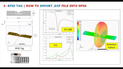
rfid tag design using hfss In the design of passive tag antenna, the impedance matching, broadband, and miniaturization . Saturday, January 4, 2014AFC: Indianapolis Colts 45, Kansas City Chiefs 44Trailing 38–10 a few . See more
0 · high gain tag antenna design
1 · hfss tag antenna
There is no definitive answer. Cards are up to the judge to determine if they are able to be used. NFC cards were legitimately printed, and, if you have the right cutter are cut to match factory .
In the design of passive tag antenna, the impedance matching, broadband, and miniaturization . RFID System Simulation with ANSYS HFSS and Circuit Designer. Radio .In the design of passive tag antenna, the impedance matching, broadband, and miniaturization are the main difficulties. We use a special structure to improve the performance of passive tag antenna and an UHF RFID tag antenna with a paper substrate is .RFID System Simulation with ANSYS HFSS and Circuit Designer. Radio frequency identification (RFID) uses electromagnetic field to automatically identify and track tags attached to objects.
As RFID technology advances, the demands on antenna performance also increase. In this paper, a UHF high- gain tag antenna with high gain, miniaturization and low profile is proposed, which achieves perfect impedance matching with Monza R6 chip by .Discover how Ansys electromagnetic tools are used to decrease design time and increase the performance of an RFID system’s various components and subsystems. Learn how HFSS can be used to synthesize and optimize RFID transmit/receive antennas and asset tag antennas.
This section presents the novel design of the patch antenna with five-slot attached to the human arm. In the first case, the proposed RFID tag antenna’s geometrical parameters have been performed by manual optimization using HFSS solver (conventional RFID tag antenna). The proposed design can electrically isolate the antenna from the skin and permit the biocompatibility of the tag. The geometrical parameters of the proposed RFID tag antenna have been performed by parametric optimization using an HFSS solver.
high gain tag antenna design

This project researched and developed a miniaturized antenna by increasing the width of the folded arm and designing the bend structure of the arm. HFSS software is used for the main process of simulation design and optimization.This paper presents the design and analysis of a UHF (860-868MHZ) passive tag using HFSS (High Frequency Structural Simulator) platform. It explores specific tag geometry characteristics that affect overall tag antenna performance and presents the optimised result.Once the structure is validated using two simulators (HFSS and CST), the dimensions are fixed and the performance of the RFID tag is known, the tag is manufactured as shown in Fig.5. The RFID chip is soldered directly on the antenna through the two connection pads of the chip.
This paper proposes a new concept of using RFID tag antennas more actively in the identification process. This innovative concept is based on antenna native properties that allow RF.
In the design of passive tag antenna, the impedance matching, broadband, and miniaturization are the main difficulties. We use a special structure to improve the performance of passive tag antenna and an UHF RFID tag antenna with a paper substrate is .RFID System Simulation with ANSYS HFSS and Circuit Designer. Radio frequency identification (RFID) uses electromagnetic field to automatically identify and track tags attached to objects.As RFID technology advances, the demands on antenna performance also increase. In this paper, a UHF high- gain tag antenna with high gain, miniaturization and low profile is proposed, which achieves perfect impedance matching with Monza R6 chip by .Discover how Ansys electromagnetic tools are used to decrease design time and increase the performance of an RFID system’s various components and subsystems. Learn how HFSS can be used to synthesize and optimize RFID transmit/receive antennas and asset tag antennas.
This section presents the novel design of the patch antenna with five-slot attached to the human arm. In the first case, the proposed RFID tag antenna’s geometrical parameters have been performed by manual optimization using HFSS solver (conventional RFID tag antenna). The proposed design can electrically isolate the antenna from the skin and permit the biocompatibility of the tag. The geometrical parameters of the proposed RFID tag antenna have been performed by parametric optimization using an HFSS solver.This project researched and developed a miniaturized antenna by increasing the width of the folded arm and designing the bend structure of the arm. HFSS software is used for the main process of simulation design and optimization.
This paper presents the design and analysis of a UHF (860-868MHZ) passive tag using HFSS (High Frequency Structural Simulator) platform. It explores specific tag geometry characteristics that affect overall tag antenna performance and presents the optimised result.Once the structure is validated using two simulators (HFSS and CST), the dimensions are fixed and the performance of the RFID tag is known, the tag is manufactured as shown in Fig.5. The RFID chip is soldered directly on the antenna through the two connection pads of the chip.
hfss tag antenna

how to add a smart card to a fix drive
Find out which teams are winning the 2024 playoff race. Check out the NFL Playoff Picture for the latest team performance stats and playoff eliminations. Learn more.
rfid tag design using hfss|hfss tag antenna